
Oil Separators for Water Treatment
Oil Separators for Water Treatment
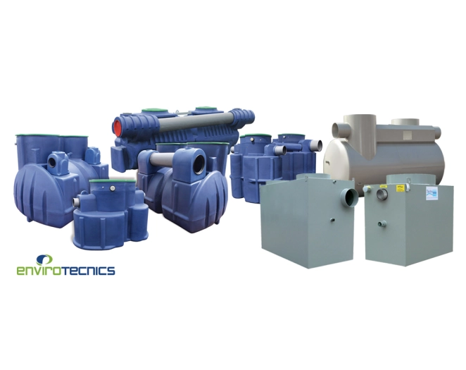
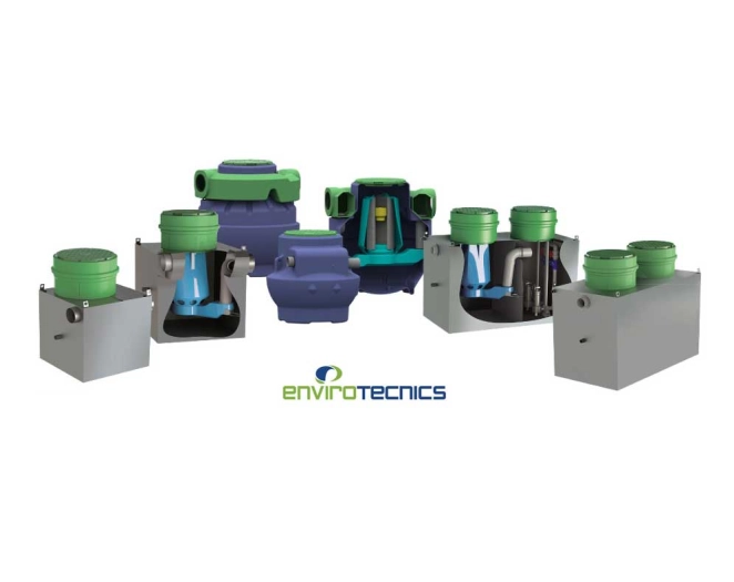
Hydrocarbon separators are systems designed to treat contaminated water by separating oils, fuels, and other hydrocarbons, preventing their discharge into the environment.
Hydrocarbon separators are wastewater treatment equipment that remove oils, fats, fuels, and other petroleum-derived substances present in contaminated water. They operate through physical separation processes based on density differences, where hydrocarbons, being lighter than water, rise to the surface to be retained and subsequently extracted.
These systems are essential in industrial facilities, service stations, mechanical workshops, parking lots, and areas where there is a risk of contamination from hydrocarbon spills. Their use helps to comply with environmental regulations and protect aquatic ecosystems.
Components
Settler
This compartment, located before the separation chamber, is intended to settle heavy materials (sludge).
Separator
The separator compartment of the retention chamber allows free hydrocarbons to rise to the surface. It thus enables the storage of recovered hydrocarbons.
The bypass
A hydrocarbon separator with bypass allows for the absorption of larger flow rates in case of a storm, up to 5 times the nominal flow rate. A nozzle allows for the treatment of the expected nominal flow rate for which it is designed.
The automatic shutter
Each device in the range is equipped with an automatic shutter device to prevent any discharge into the natural environment. Its operating principle is also based on the density difference between water (density 1) and light liquids (density 0.85). Thus, the automatic shutter floats on water while, in hydrocarbons, it sinks. When the hydrocarbon layer is thick enough, the device's outlet is blocked. The coalescing lamellar cell
A coalescing system is used to improve the purification performance of the device. This procedure allows for a discharge level of less than 5 mg/l. The effluent transits from the bottom to the top, promoting the flotation of free hydrocarbons with a density of 0.85. Hydrocarbon particles suspended in the water adhere to the back of the lamellae and form a hydrocarbon film that migrates from bottom to top.
- Service stations and gas stations
- Underground and public parking
- Mechanical workshops and automotive
- Petrochemical industries
- Vehicle wash stations
- Airports and logistics areas
- Industrial areas with spill risk
- Port facilities
Classification in the attached catalogue
• Settler & Coalescing Filter.
• Settler, Coalescing Filter & bypass.
• Large Settler & Coalescing Filter.
• Coalescing Filter.
• Settler, Coalescing Filter and Pumping Tank.
• Acid Neutralization Tank.
• Hydrocarbon Separators Sizes > 35 l/s.
• Settler, Coalescing Filter.
• Settler, Coalescing Filter, bypass.
• Rainfall Intensity.
- The implementation of hydrocarbon separators is subject to the EN 858 standard.
UNE EN 858-1 - Principles for design, manufacturing, testing, marking, and quality control.
UNE EN 858-2 - Installation of light liquid separators.
It is based on the density difference between elements inside the separator. Light liquids, with a density of 0.85, rise to the surface, while heavy materials, with a density of 1, settle at the bottom of the device.
- Protection of the environment and water resources
- Compliance with legal regulations
- Reduction of industrial discharge impact
- Low maintenance cost
- High efficiency in oil separation
- Long system lifespan
- Adaptability to different flow rates and sectors
Models
-
HC 25 PE Oil Water Separator for Water Treatment (25 l/s)
Ref. 8200000000335
-
HC Hydrocarbon separator 6 l/s reinforced PE
Ref. 8200000000166
-
Hydrocarbon separator HC 1.5 l/s reinforced PE
Ref. 8200000000173
-
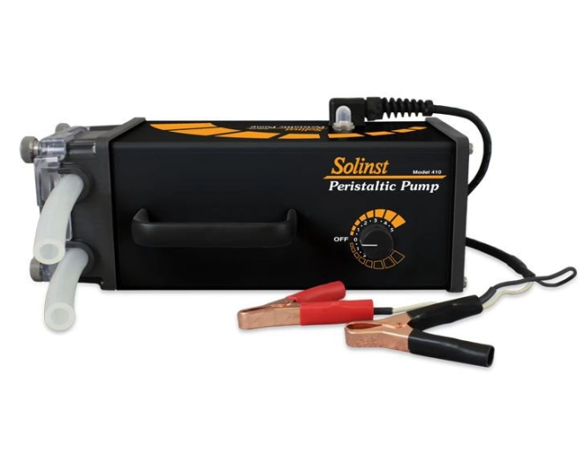
Ref. 2100000000059
Not available
Not available for this country
-
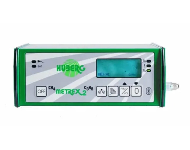
QED METREX 2 Portable CH4 Gas Leak Detector
Ref. 3100000000155
Not available
Not available for this country
-
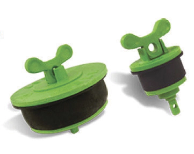
Expandable plug for gas sampling 4"
Ref. 3100000000071
-
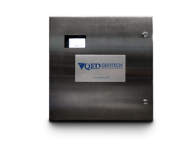
Biomethane 3000
Ref. 3100000000241
Not available
Not available for this country
-
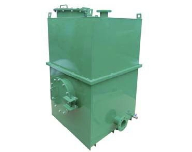
Active carbon air filter
Ref. 8200000000279